Wednesday, September 2, 2009
Wow its been a long time since I have posted anything up here. I have been busy at college and just got home a little over a month ago for a while and I have been itching to do a mod so here we are.

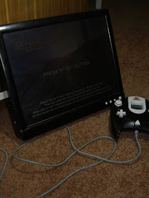
A few weeks ago I Soft Modded a friends Xbox for him and installed a 250GB hard drive and put on XBMC for him and in return he gave me his older Xbox which was a failed attempt to Hard Mod an Xbox. So I took it and a week later this is what I had.


It has an Xecuter 3 Mod chip in it. I flashed the Mod Chips Bios with Xecuter X3 and the back up Bios (pressing both eject and power at the same time) is FlashBios which gives you the ability to reflash your bios if you screw it up.


The Xbox Hard Drive has been upgraded to a 120GB hard Drive and is running XBMC. A great feature is that if you hold the power button the Xbox will boot up on the original Bios with the Mod Chip off and it will boot to the original Xbox Dash allowing you to play Xbox Live.


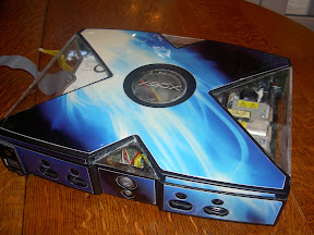
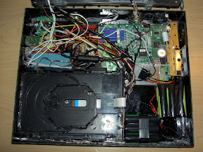
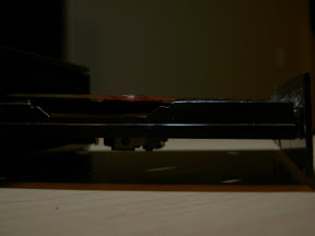
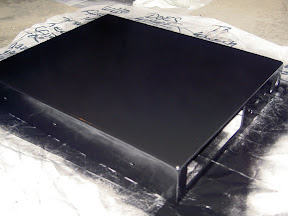
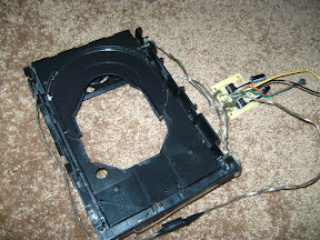
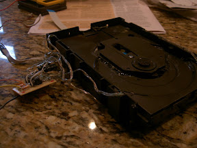
The case underwent weight loss and with the removal of the DVD Drive is an Xbox Slim. Gap where the DVD Drive would have been has been removed and now is approx. 1/2" thinner than the original case. The DVD drive can still be plugged in to rip your media to the Xbox as well as when you want to play Xbox Live enabled games because on the original Bios the Xbox won't boot up properly without it connected.


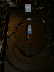
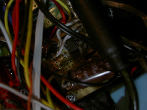
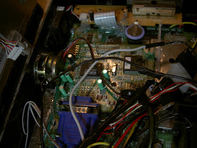
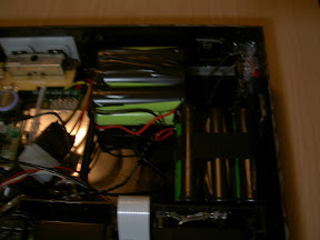
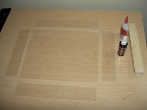
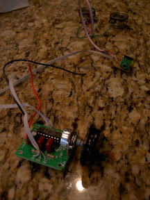
I have also added windows all around the Case. The other pictures show alternate views of what the windows look like from different angles but here you can see the Hard Drive as well as the IDE plug for the HD as well as the DVD Drive. The mod chip is sitting underneath the HD. As seen in the other pictures the XBOX jewel on the top of the case has been cleared as well allowing one to see into the Xbox.

The decals and the Mod Chip were both installed prior to my obtaining of the Xbox.

Back up and Running!

Wednesday, April 1, 2009
Well i got all of the pictures back up! Hopefully this time everything works out and there won't be anymore blank pictures. Anyways I got more pictures to put up so here they are. It's the Dream Tablet running Power Stone.

From Dreamcast Laptop


From Dreamcast Laptop


From Dreamcast Laptop


From Dreamcast Laptop


From Dreamcast Laptop

Fixing Pictures

Hey sorry everyone for the down pictures! Seems as if I have more viewers of my blog than I thought. My whole bandwidth was used in a day... So I am changing Image hosting websites and doing some things to help keep the bandwidth usage down. The pictures should be up soon!

DONE!

Sunday, March 29, 2009
Got the Tablet done and I decided to name it the Dream Tablet. It is powered by a 14.8v 6600 mah battery which is nice and big and should get a pretty decent play time off of it. Also you can play and charge at the same time so it makes things nice. Here are the final pictures.

From Dreamcast Laptop
Inside

From Dreamcast Laptop
GD-Drive

From Dreamcast Laptop
Circuit that controls GD-Drive

From Dreamcast Laptop
Audio amplifier

From Dreamcast Laptop
Screen controller board with Sega Dreamcast underneath it

From Dreamcast Laptop
Pico Psu

From Dreamcast Laptop
Battery

From Dreamcast Laptop


From Dreamcast Laptop


From Dreamcast Laptop


From Dreamcast Laptop


From Dreamcast Laptop

From Dreamcast Laptop


From Dreamcast Laptop


From Dreamcast Laptop


Next to an Xbox 360 for comparison.

Case

Saturday, March 21, 2009
I had a few ideas on how I wanted to make the case. Originally I wanted to vacuum form it and make a wood mold with rounded edges to make it look nice. But I didn't do that. I went to home depot again and bought a sheet of acrylic. This method worked well for me. I got some more of the Insta-set but this time I got Maxi-cure. It had a slightly longer cure time then the stuff I used on my portable and it was a little cheaper. But I must say that I do not like it as much as the stuff I used on my portable.

The dimensions for my case are 13.5" x 11" x 2". Not bad I thought for having the GD drive and the screen resting on top of that! I cut out the pieces with a 10 inch table saw this time with a 200 tooth blade. It worked very well and I got very straight clean cuts.

From Dreamcast Laptop


I glued all the pieces together and got the bottom part of the case assembled. To make sure that my pieces were perpendicular to each other I took a piece of wood and used it to hold my pieces against.

From Dreamcast Laptop


From Dreamcast Laptop


After the case was assembled it was time to make the holes all of the ports, GD drive and the volume knob. I used my dremel with a cutting disc to cut out the GD drive hole and then used a file to make sure I had nice straight lines.

From Dreamcast Laptop


The power switch, and AV/monitor switch I used my dremel and then used a small file to ensure straightness. For the volume I used the hole saw again. The rest of the ports I used a drill. As well as for the speaker holes and I used perf board as a templet as many others do.

After everything was set i began to paint. It is now black instead of clear.

From Dreamcast Laptop

Screen

So rather than going with the LED mod as I don't think it would saved me much power I decided to stick with the original back light in the screen. I used the Dell E153FP 15" LCD monitor. I opened it up and removed the original power/inverter board (they were all on one) and got the Controller board running on the Pico PSU. Here are two pictures of the controller board, the top and the bottom where power must be connected.

From Dreamcast Laptop


From Dreamcast Laptop


In order to get the controller board working you must connect 3.3 volts to the two pins that the red wire is connected to in the picture. And then ground is the black wire. The other pins I believe are for sending information back to the inverter and such.

The inverter that I am using is one taken from a ccfl light kit for PC lighting. It runs on 12volts and produces enough light with the original ccfl tubes to make for a very bright screen.

For the top part of the case I decided to use the front of the case from the monitor since the cut out for the screen was already exactly the right size. I just had to cut off some tabs on it to get it to fit onto my case. I didn't like the finish on it though because after I painted it, since the finish was different then the acrylic I was using I would most likely end up with two different results. So I put a wire brush attachment onto my dremel and commenced to remove the finish. I then used a sponge sander, used for drywalling, to bring it to a smooth finish. Painting turned out well. I also painted the buttons for use with it. They are a little off white as to contrast against the black case. They turned out well. Here are some pictures of the result with the case glued to the screen.

From Dreamcast Laptop


From Dreamcast Laptop


To mount the screen to the rest of the cast I glued 8 90 degree metal braces to the back of the screen. I glued a nut to the inside of the brace so that the front can be screwed onto the rest of the case from the sides. I also did this to make the screen removable for debugging after everything was assembled.

From Dreamcast Laptop


From Dreamcast Laptop

There are 8 metal braces in total.

Sound

For sound I used a kit that was suggested to another member of the Benheck forum community. I figured that it would suit my needs and so I went ahead and got it. It is a stereo 1W amplifying circuit. I put it together and everything works great. I'm using 2 4ohm speakers from a Dell sound bar. I'm pretty sure that thing was never meant to be opened. It had 6 or 7 screws in it but even after removing them all, examining it for several hours, and prying on cracks I couldn't get it open. I finally took out my dremel with a cutting disc and started cutting it up. The amplifying IC can run off a wide range of voltage so I decided that since I was using 2 4 ohm speakers rather than the recommended 8 ohm that i would use 5 volts. It works great.

Here are some pictures of the set up with the head pone jack attached as well. When head phones are plugged in sound through the speakers is turned off. The headphone jack works great.

From Dreamcast Laptop


I didn't want to just use the metal post from the potentiometer for volume control cause it wouldn't match the style of the tablet. I also didn't want to salvage a knob from something else because they didn't match what I wanted either. I wanted something that had a larger diameter and wasn't very thick. The only possession of mine that I could find that had a knob I could use was in active use. So I settled on making my own knob. I used a hole saw and cut out 3 pieces of acrylic that were the same size, and then one more of the next size up so that it would have a backing. I glued them all together, put a notch in it with my dremel and painted it. It turned out really well. Here are the final results.

From Dreamcast Laptop


From Dreamcast Laptop

(ignore the dust on it, it was stuff that settled on it after painting was complete)

GD-Drive slimming

After I got the GD-Rom onto the tray I decided that it was too tall for my liking. I cut out more from the tray and flattened the remaining plastic on the GD-Rom. I did ave a little bit of a problem because now that the GD-Rom sat so low it would hit across the bottom of the tray. Just flattened the bottom out a little bit and all was well. Here are my results.

From Dreamcast Laptop


From Dreamcast Laptop


From Dreamcast Laptop

(GD-Rom disc does no come above sides of the tray)

As you can see in the pictures I put all of the components for the circuit onto a perf board.

GD Drive

Wednesday, February 4, 2009
Ok so after I got the CD-Drive working I needed a way to mount the GD-Rom onto the CD-Drive tray. At first my thought was to mount it underneath which would keep the thickness down. Unfortunately as I was thinking about this I decided that this was probably not the best idea because the method in mounting it to the CD tray was using glue. So If someone was a little frustrated they could push too hard and could possibly push the drive off the tray. It would also cause me to have to remove one of the major support beams that connect both sides of the drive mechanism. If I went this method I would have to cut that off and then reinforce it in another way.

So then I thought about placing it on top of the tray. Obviously it wouldn't fit but that is where my good friend the Dremel comes in. I put a disc on my GD-Rom and made a rough trace of it and put it on top of the tray and commenced to dremel. Here was my final product.

From Dreamcast Laptop
CD-Tray cut out.

From Dreamcast Laptop
With the GD-Rom on it.

From Dreamcast Laptop
GD-Rom and CD

I decided to go this route because it would be less of a hassle. More structurally sound, and it didn't add very much height to the system.

GD Drive schematic

Ok so I got the CD-Drive working. For a while now I have been trying to figure out how I was going to get it working and had a few ideas and built a couple prototypes and have finally settled on one that works completely. It uses two 555 timers and 4 sensors, and one button to open and close the drive.

From Dreamcast Laptop

Here is the schematic.

So basically how it works is you have one of the 555's to control when the tray goes out and the other for when it goes in. The 555 that makes it go out, you put the switch/sensor connected to pin 2 of that 555 on the closed side of the tray so that when it is closed it pushes the switch. Put the switch that is connected to pin 4 on the open side so that when it is open it pushes the button/switches the switch.

Then for the 555 that closes it do the opposite. Put the switch connected to pin 2 on the open side and the switch connected to pin 4 on the closed side. Basically what happens is when it is closed you push S1 and that triggers the open 555. When it is open it pushes pin 4 of the opening 555 and resets it sending it back to 0v. It pushes the button connected to pin 2 for the closing 555 so when you push S1 it triggers the closing 555. When it is completely closed it pushes the switch connected to pin 4 of the closing 555 and it sends it back to 0v.

One of the problems I had with this at first was I didn't have the capacitors on it at first and for some reason the circuit would work until I hooked the motor up to it and I'm thinking that the motors induced voltage after it got shut off would cause the 555 that performed the direction opposite to the way it was going (so when it got completely opened it would instantly trigger the closing 555 and begin to close). This would go on endlessly until you took away the power. So I was trying to think of a new way to do it and then I thought about putting in the two capacitors and it worked. Later on I had to switch out the capacitors for some larger 3300uf ones instead because 1000uf didn't seem to be enough. Hooked it up to 12v and all worked.


Video of it working.